Chapter 5 - Y-Carriage Construction
It is time to start the Carriages. I am glad because I would like to see some moving parts and this at least gets me started.
Material for KRMx01 Y Carriages
 Here I have the pieces of angle iron cut for the carriages. These are 2" x 2" x 3/16" and 1" X 1" X 1/8" material.
Marking and Punching the Angle Iron

 After cutting the angle iron to the size specified in the book, it was time to mark and center punch it. I have always had a hard time marking angle iron so that I could see the mark clearly. For fine measurement I have had a bit of difficulty getting the mark where it should be with the tools I had on hand. My solution to this problem was to paint a light coat of flat white paint on the angle iron and use the height gauge pictured in the second image to scribe my marks. This worked incredibly well for me. The gauge is was $60 dollars I think and will measure up to 6" in .001" increments. It is Chinese made, so I don't know the quality of it, but does a fine job for what I bought it for. Once I zeroed the gauge, I would simply set it to the height I needed and pull the angle iron across the carbide tip scribing the line. Just thought I would pass that along.

 With the marking and punching out of the way, the KRMx01 Y-Carriage tops and bottoms were drilled, tapped and the slots cut for the v bearings. The second picture shows the KRMx01 Y-Carriage supports. I have deviated from the book here. The reason for this was the new anti backlash nuts from cncrouterparts.com is different from the original. The original nut was an all plastic unit. The new nut is contained in an aluminum housing. These nuts ship with 5/16-18 socket head bolts. In order to have some room for adjustment, I drilled the two center holes at 3/8" rather than the specified 5/16"
Some notes on the Anti-backlash nuts
The original plans for the KRMx01 CNC machine called for cncrouterparts.com part #CRP109-00 and has been replaced by part #CRP161-00-02. The difference between these two products are minimal and I have included links below so that you can view the associated PDF documents on them. The only major difference between the two nuts that need to be taken into account are the total height of the assembly. The original #CRP109-00 assembly is 0.825" and the new #CRP161-00-02 assembly is 0.980". The difference in height between the two is 0.155". Because of the close proximity of the nut to the Y-Beams, a spacer of about 1/16" will need to be placed between the Y-Carriage supports and the Y-Carriage Top and Bottom. In a post on the CNCZone Kronos forums, Michael Simpson, the author of the book, had this to say:
It looks like CNC Router Parts has pulled the original nut.
In any case the new nut is not a direct replacement. The problem is that it needs more clearance. You need about 1/16" more clearance for the nut to keep from hitting the Y-beam. I did this by inserting a small piece of 1/16" thick aluminum between the supports and the main frame.
Refer to Step 7 in Chapter 5. I cut a small piece of aluminum 1" x 2" x 1/16" from 1" x 1/16" aluminum bar. You will need to mark the holes to match those in the main frame and support. You will need four of these for each carriage When installing the supports to the main frame, the aluminum spacers go between the two. This will pull the supports about 1/16" further away from the beam when the carriage is attached to the rails. As for the screws I still used the 1/4" bolts. You can use the 5/16" bolts but will have to drill larger holes. If in doubt use 1/4" bolts.
The motor/bearing mounts have enough play that you should be able to easily compensate for the 1/16" difference before tightening.
It has been awhile since I did this mod so keep us informed.
The key is to have a little play so you can line up the nuts.
![]() Click the ICON to the left to download the cncrouterparts.com part #CRP109-00 specification sheet.
Click the ICON to the left to download the cncrouterparts.com part #CRP109-00 specification sheet.
![]() Click the ICON to the left to download the cncrouterparts.com part #CRP161-00-02 specification sheet.
Click the ICON to the left to download the cncrouterparts.com part #CRP161-00-02 specification sheet.
Painting the KRMx01 Y-Carriage
 The angle pieces are painted and ready to be assembled, well sort of. They need to cure for a bit for the paint to harden, the bearing adjuster holes need the tap run back through them to clean the paint from the threads and I need to cut the above mentioned spacers to go between the carriage support and the top and bottom pieces. Other than that, well we are golden! :-)
Making the Spacers

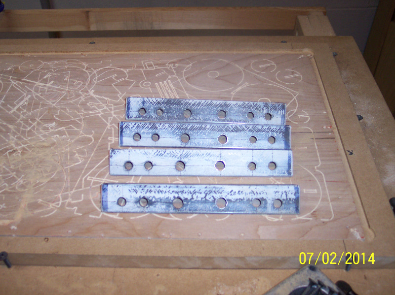
 I thought I would assemble the carriage without spacers to try to get an idea of how much I needed to go. Just trying to eyeball it, I thought the 1/16" spacers would do the trick. I decided I would use 1/4" washers for the spacers, they were just a little over 1/16" and I thought, what the heck. That would be a simple fix and everyone has access to washers. I took the callipers and measured a bunch of them until I found 8 that I felt were close enough to the same size. I assembled the carriage again for another test fit. Hmm ... it was still hitting the Y-Beam, but just barely. So, I thought I would do it different. I cut 8 pieces of 1/8" x 1" strap 2" long. The image on the left shows the pieces I cut. (By The Way, my wife is a little OCD, so I thought she would love this picture!) Next, I coated them with some flat white Krylon spray paint so I could easily marked them. You can see this on the image to the right.

 Next I marked and punched the centers. The lines are marked like the Y-Carriage supports, a line is scribed 3/8" from the edge, and then cross lines are made at 3/4" and 1-1/2" from one end. The image to the left shows them scribed and punched. Next, I piloted all the holes with an 1/8" drill bit and then drilled them 5/16" just like the Y-Carriage support pieces.
 Finally the spacers have been painted and when dried well I can continue on with the assembly of the Y-Carriages. One thing that should be noted is that by using these spacers the center points of the bearing and motor blocks will be off. Since I have not cut these items yet, I will redraw them moving the motor/screw centerline by 1/8" for the Y axis. Similar steps will have to be done for the X-Carriage and Z-Carriage assemblies.
![]() For a drawing of the spacer, please click the DXF icon to the left.
For a drawing of the spacer, please click the DXF icon to the left.
Assembling the Y-Carriages
 Now that the spacers for the Y-Carriage supports are finished, I can start assembling them. The part list is the same except for the anti-backlash nuts. The new nuts come with socket head 5/16-18 bolts. I am using these rather than the suggested 1/4-20 bolts from the plan. I am using 1/4" flat washers, 5/16" lock washer and 5/16" nuts with these. Remember, I modified the supports by drilling 3/8" holes for the two center holes to allow some room for adjustment with the larger 5/16" bolts.


 The assembly of the Y-Carriage is exactly the same as in the book with the exception of placing the spacers under the Y-Carriage support pieces. Since the spacers were cut using the same layout as the support, you will need to pay attention to how the spacers fit into place so they do not extend past the support piece. The images to the left show everything in context.
 The KRMx01 Y-Carriage assembly is now completely assembled. Next they will need to be fitted to the Y-Axis beams and adjusted so they are both parallel and at the same height to each other and the beam. We are getting close. I feel the X-Beam coming on!!! :-)
![]() For a detailed guide on assembling the KRMx01 Y-Carriages, download the Assembly Guide PDF by clicking the ICON to the left.
For a detailed guide on assembling the KRMx01 Y-Carriages, download the Assembly Guide PDF by clicking the ICON to the left.
Fitting and adjusting the Y-Carriages

 Fitting the carriages to the Y-Beam rails was a pretty straight forward process. Loosen the lower adjusting bolt and back it out enough for the bearings to slide on the rails. The tedious part was adjusting them to the same height, well at least to about .001". Both carriages are the same height from the top of the Y-Beam and both the front and back of the carriages are the same height. This little height gauge came to the rescue again. I am using the plate that will become part of the Z-Axis to hold the router clamp as a base for the tool.
The Finished KRMx01 Y-Carriages

 Here is the machine with the carriages attached, levelled and ready for the X-Beam.
See you in the next chapter. :-)